Overview
The W2MMD satellite station at the Gloucester County Amateur Radio Club’s clubhouse is pretty close to state of the art. We have the top-of-the-line M2 satellite antennas, an SDR Play receiver for copying the downlinks, PST Rotator software for rotator control and Doppler correction and an aging Yaesu 847 transceiver used only for transmitting. With this station we were generally successful on most amateur radio satellites, so we thought we’d have a good shot at Greencube. But there are some important differences in Greencube operation that we hadn’t realized at the start but that became quite evident as our levels of success did not reach what we had hoped. This article describes some of our more important learnings throughout the process and the changes that we made to our operations and equipment configuration that led us to a higher level of success with this satellite.
Use the proper frequency offset
The published frequency for Greencube uplink and downlink is 435.310 MHz, so we initially set PST Rotator to those frequencies and clicked on the UP+DN button to track the Doppler shift, but this didn’t get the received signal in the SDR Console bandwidth window so we had to constantly tweak the right and left arrows to keep the received signal in the window. After some online research that lead to conflicting opinions, we set both the uplink and downlink frequency to 435.309.200 Hertz (see Figure 1), which puts the received signal dead center in the bandwidth and also apparently puts the transmit signal at the correct frequency offset to be received by the satellite. We no longer have to tweak the frequency – PST Rotator now keeps the received signal solidly in the receive bandpass.

Figure 1- PST Rotator frequency settings
Set the receive filter bandwidth right
PST Rotator has a number of preprogrammed bandwidth filters, which we weren’t sure how to use correctly for this satellite. We needed a filter wide enough to completely receive the signal when tuned to the proper frequency, but we also wanted to eliminate noise outside of that signal. After some trial and error we created a Greencube filter in SDR Console set between 700 and 2100 Hz that seems to work pretty well.

Figure 2- Greencube filter in SDR Console
Set Soundmodem correctly
Before we got the received frequency correct we were tuning around in the Soundmodem window trying to get the blue and red arrows between the received signal peaks. Depending on the receiver offset those peaks would center anywhere between 800 and 1200 Hz. Once we got the receive frequency dialed in correctly we could set the center frequency in Soundmodem to about 1500 Hz and leave it there. PST Rotator would adjust for Doppler shift and would keep the signal within those points in Soundmodem, so we never had to touch it again.
Use a preamp
Having a 22 element crossed yagi we figured we had enough antenna that we wouldn’t need a preamplifier to receive the Greencube signals, and we were successful about 80% of the time. But many times near the beginning or end of a pass the signal level would drop below the level needed to decode it, which was frustrating because most of the interesting stations are within the satellite footprint at the extreme ends of the pass. Adding a mast-mounted preamp brought the signals up to a level that we could copy throughout almost an entire pass. Even that large antenna benefited from preamplification to push the signal through the feed line going from the antenna to the radio.
Use enough power
Our venerable Yaesu 847 combined with our antenna gain has been sufficient to work most low earth orbit satellites, but we frequently weren’t seeing our replies on the downlink of Greencube. Checking the power output showed we were only getting about 15 watts from the radio, and some online reports showed many users utilizing the Icom 9700 radio which has output of about 70 watts. This led us to conclude that we needed more power on the uplink. One of our team members was able to contribute a Yaesu FT991-A transceiver that runs about 50 watts, which significantly improved our uplink hit rate.
Remember that the earth is a sphere
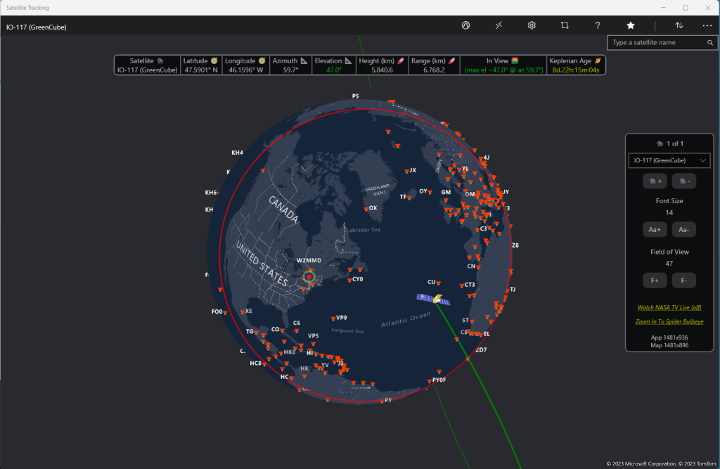
Most of the maps in satellite tracking programs use flat projections of the earth that show the footprint of the satellite to the west or east of the station’s QTH. This works well for LEO satellites with a relatively small footprint (see Figure 1) but it’s confusing and often misleading for an MEO satellite like Greencube that has a huge footprint (see Figure 2). This means that stations both to the east and east of you maybe within the footprint at the same time. If you’re looking for stations in a particular area, as we were for stations in Japan, it’s difficult to predict from these maps when those distant stations will be within your footprint. Programs like “Satellite Tracking” program available in the Windows Store visualize the earth as a sphere that can be rotated, properly showing the footprint as a circle on the earth. This allows you to easily see which stations will be within the satellite’s footprint.

Figure 3- Flat depiction of a LEO satellite

Figure 4- Flat depiction of a Greencube pass


Figure 5- Satellite Tracking program
Note that PST Rotator will miss Greencube passes
For some reason PST Rotator doesn’t recognize some Greencube passes. It doesn’t show them when counting down to the next pass, and during a pass it doesn’t show the time to LOS (see Figure 6 showing a positive elevation with a countdown to AOS, not to LOS). It does, however, properly set track the satellite throughout the pass. We realized this when cross checking upcoming passes with a different program. So if you’re looking for upcoming passes use something different than PST Rotator to be sure you don’t miss any.

Figure 6- PST Rotator missing Greencube pass
