How We Built the GOES Reception Project


How We Built the GOES Reception Project

Updated 12/1/18
Building our functional GOES 16 receiver was a process of broad web research and cobbling together the experiences of many other successful experimenters. We found lots of individual articles on antenna selection, software, and many other topics, but nothing that really pulled everything together. Hopefully this article will provide a comprehensive overview of our project. If you’ve found other tips that were useful or have questions or comments about the project, please leave them in the Comments box below and we’ll try to reply when possible.  Thanks to the many experimenters whose work we copied and implemented in making this project work.

Location (QTH)

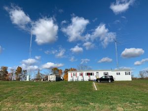
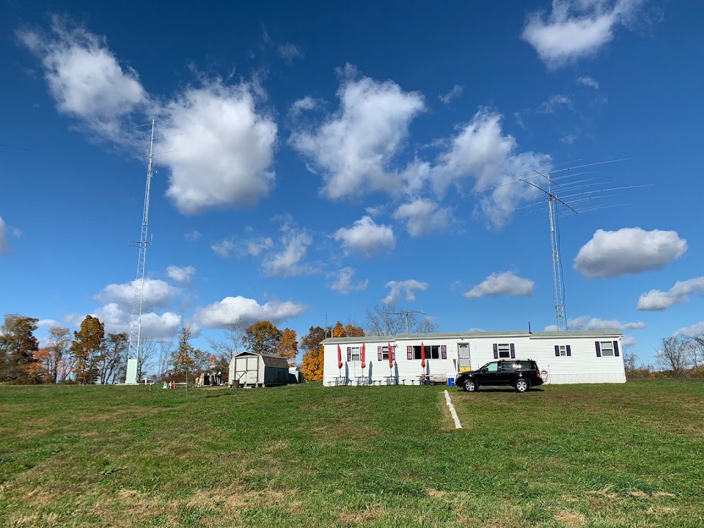
Our station is located at the “clubhouse” of the Gloucester County Amateur Radio Club, located in Mullica Hill New Jersey. The clubhouse provides a dedicated location for radio experimentation and radio operations, complete with a 100 foot tower for VHF antennas, a 55 foot crank up tower for HF antennas, and a 10 foot tower for satellite antennas that don’t need elevation because they’re pointed at radios orbiting the earth. Hams and other radio experimenters in the southern NJ or Phila area who are interested in these projects are welcome to join our group – see w2mmd.org for information about the GCARC.
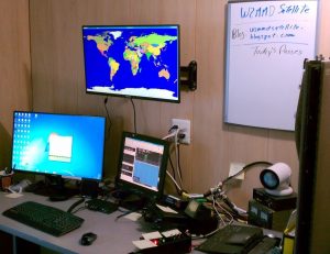
Here’s a shot of our satellite station. Much of this equipment is used for amateur radio satellites, but we used the computers and some other equipment for the GOES project. We have lots of different satellite-related projects going on and blog them in http://w2mmdsatellite.blogspot.com/ for anyone who’s interested.

GOES Antenna

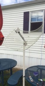
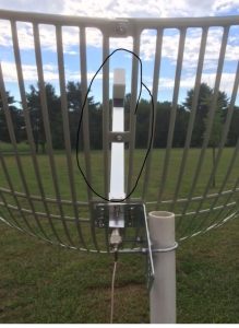
Many experimenters apparently used Wi-Fi dish antennas for these projects, but I was concerned about the frequency disparity between those antennas and the freq of the GOES satellite. Therefore, we selected this antenna, which is more closely tuned to the GOES frequency (note – it appears that this antenna is no longer available on Amazon, and we haven’t tried the replacement). I did some initial experimenting with it on a tripod, but found that the tripod couldn’t maintain the aiming accuracy necessary. It’s currently tie-wrapped to a picnic table in front of the clubhouse, but its eventual location will be on the small tower next to the clubhouse. Note – this is now done.
Antenna aiming is critical– we found that an error of more than about 10° significantly degrades the signal. The clubhouse is located at about 39° north latitude and 75° west longitude, which places it almost directly north of the GOES 16 satellite; therefore our antenna should be aimed pretty close to true south. We found this website provides some useful information about antenna aiming, but this one gave an actual picture (below) of the sightline for the antenna from our property. That was invaluable in getting the antenna aimed correctly. Remember that magnetic north is different from true north, and that difference will prevent getting a usable signal, so don’t use a compass heading for antenna aiming without correcting for that error.
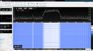
Based on this info we got the antenna pointed almost perfectly, and then made manual adjustments for maximum signal strength to fine-tune it (see the image below for how a strong signal should look in SDR Console). Once we got it right, I took the picture through the antenna so that it could be repositioned easily. The center of the antenna needs to be slightly to the left of the tall tree across the road.
Also – we were initially confused about the orientation of the antenna since one article suggested that it should be horizontal, but instead should be tilted at about a 45° angle. We tried various orientations, but horizontal seems to work best. Then we figured out why – the orientation of the antennas on the satellite are tangential to the arc of the orbit. When the satellite is it the same longitude as the receiving station, as it is for us, the antennas will be horizontal. However, if the receiving station is east or west of the satellite the receiving antenna will need to be tilted to accommodate the tilt of the satellite’s antenna. This reference may give information about antenna tilt, but we didn’t need it. Note – Dana Howard pointed out on the AMSAT Facebook page that although the antenna reflector is horizontal, the dipole within the small plastic housing is vertical. Thus, I may have confused “horizontal” with “vertical” in the above description; however I think most readers may not know that difference and may refer to the reflector position, which for our location is horizontal.  Thanks to Dana for the explanation. 

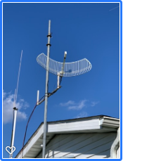
We finally got it installed on the pole next to the clubhouse, where it will remain. 


Start with SDR Console

You can’t start out working with the GOES software described below – you need to use a standard SDR program to assess signal strength and signal to noise ratio (SNR) to check out the RF hardware and get the antenna aligned. Below is how a strong signal looks in SDR Console. Don’t make the initial dumb mistake that I did and tune SDR Console to too narrow a bandwidth setting.  I did that and only got a small segment of the GOES signal – and couldn’t figure out what I was seeing. Remember that the GOES signal itself is almost 2 mhz wide (for hams, that’s half of the entire 2 meter band), so you need to set the bandwidth REALLY wide to get a view like this. Ideally the signal will be about 6 db above the noise for good decoding.

Preamp and SAW Filter

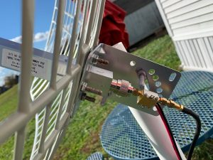
I’ve seen several articles about using lower-cost preamps, but one article showed a high-quality preamp that I chose and it performs well although it’s slightly pricey (about $100). Initially we connected it to the antenna with a short piece (1 foot) of cable having a N connector on one end and SMA connector for the preamp on the other end, but it appears that even that a short cable may have attenuated the signal from the antenna. We ended up connecting the preamp directly to the antenna through an N to SMA adapter, which seems to be better. We ended up running about 50 feet of coax from the antenna into the building, so we definitely needed an antenna-mounted preamp to push the weak signal thru all of that coax.

The only downside to the preamp is that it requires 3 VDC and doesn’t support bias tee power, meaning that it requires a separate power feed. Initially we powered it with a pack of two AA batteries, which we later replaced with 2 D batteries. Obviously this isn’t a long-term solution, but it worked for a few weeks while we were getting things going. Our current attempt is to use a modified solar lamp below that runs on 3 V – I stripped out the LEDs, soldered a power cable directly to the battery connectors and then connected it to the preamp. If that works, we’ll mount the lamp on the roof of the clubhouse and won’t have to run a preamp power cable all the way into the building. Note – we finally abandoned the solar power idea and ran a cable to the preamp. It appears that the solar lamp battery has enough capacity for short intervals of LED light and can’t handle the steady draw of the preamp.
Most successful experimenters were using this SAW filter, so we ordered one and put it in line after the preamp. Initially we used a short (6″) cable connection between the SAW filter and preamp which placed the SAW filter outside, but we later found that the preamp had enough gain to to push the signal through a significantly longer piece of coax, so we were able to relocate the SAW filter inside in front of the SDR receiver. We power the SAW filter with bias-tee power that the AirSpy provides. The LED on the SAW filter indicates that it’s being powered by the bias tee in the AirSpy. The AirSpy is connected to the Raspberry Pi. 

SDR Radio

We’ve seen several different radios used, but we started with an AirSpy because we had one available and it seems to give us the best chance of success. At some point we may try a lower-priced RTL – SDR radio, but for now we’re sticking with the AirSpy.

Software

There appear to be two different options for decoding software – the Windows software from USA-Satcom and the Raspberry Pi software whose installation is described here. Long story short – we initially tried the USA-Satcom software (primarily because I’m a Windows guy and don’t know much about the Linux operating system on a Pi), but the free trial for the USA-Satcom software (which has a $100 license fee) was only 2 weeks and we couldn’t get the RF part of the project working well enough to decode with that software within that period. So we switched to the Pi software, which was pretty easy to install even for a Pi novice like me thanks to the helpful instructions linked above. We made gradual improvements in antenna aiming and cleaning up the RF component as described above and our decoding gradually improved to the point where the Viterbi score was around 200 and drops were almost consistently 0. 
At that point we downloaded the picture below, which made the whole project worthwhile. 
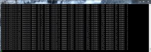
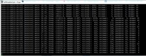
Note – the HRIT software needs to run for a few minutes before it tunes itself. (I don’t know how that process works – any clarifying comments would be appreciated.) Note below how the drop count starts out high and then drops significantly as the parameters change:

What Images are Downloaded?

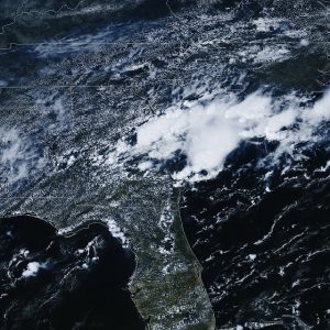
It’s amazing to see the volume of images that are downloaded each day from the satellite. There are local pictures of parts of the country:
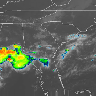
enhanced images like this:
and local infrared shots of weather events like Hurricane Michael
I was also surprised to see images from GOES-15 over the Pacific and images of Australia from the Himiwari satellite, which are apparently relayed by GOES 16. These showed up even though we’re only pointing at GOES 16. The Pi software nicely organizes the picture files into folders by satellite, channel and day, which I download daily with FileZilla for local viewing (since the GOES station is at the GCARA site I connect to that site with a VPN connection and then do the download).

More info is available from the NOAA website that displays these images. If you don’t want to build all of the stuff described here, go to that website and you’ll see the same pictures – but you won’t have the same sense of accomplishment!

Still More to Do

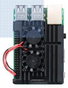
But there was still more to do. Our drop counts were still higher than we would have liked, and I saw a comment that the HRIT software really heats up the Pi, which would go into thermal shutdown and slow down the processing and thereby degrade the images. so I ordered this case, which is one big heat sink with two fans, and the drop became more consistent.

Also, a Windows guy like me had no idea how to get the images off of the Pi. Team member John O’Connell (K2QA) pointed out that we could simply use FileZilla to FTP into the Pi (port 22 was open since we were already using SSH into the Pi) and download the images to the PC. I also wrote a short WinSCP script that will download all of the new files from the Pi into corresponding folders on my PC.

John is also working on a process to back up the images to an attached external hard drive on the Pi, and eventually to a media server. John also wrote code to delete older images from the SD card in the Pi because there’s so much data that eventually the card would fill up. John also wrote code that auto-starts the goesrecv and goesproc software and figured out that we could monitor the goesrecv process by simply SSHing into the Pi and running tail -f goesrecv.log from the logs folder on the Pi. So from home I can VPN into the clubhouse, create the SSH connection using Putty and view the log to see how well the station is receiving.

The Team

The great part of working with a group on these projects is the unique knowledge and other skills that each person brings to the project. Jon WB2MNF (that’s me) has pretty decent all-around networking knowledge and can figure out basic stuff but doesn’t have the detailed RF or Linux skills that were really necessary. John K2QA knows the networking stuff really well and is well-versed in the Linux Pi world, and got a lot of the Pi infrastructure working. John K2ZA also has deep Pi knowledge as well as lots of practical experience that helped pull together disparate parts of the project.  And Al KB2AYU knows virtually everything about the radio aspects of the project, figured out the antenna orientation issue and built up the tower section that will eventually support the antenna. Working with the team really made the project successful and contributed greatly to the fun involved in making it work.

Updates

Files collected

GOES satellites download a huge number of files each day, and because it’s geostationary those files keep downloading 24/7. Add that to the large signal bandwidth (about 2 mhz – as wide as half of the ham 2 meter band) and you can see the number of bits that are flowing down each day. In about 2 months of operation we’ve received 72 gb and more then 42,000 files from GOES 16. If you’re setting up a permanent installation be sure that you’ve arranged for enough storage and that you move it off of the Pi’s SD card frequently or you’ll run it out of space.  Also remember that SD cards will eventually wear out from read/writes, so have a backup SD card ready when your current card bites the dust.

Tracking the signal and processing from the logs

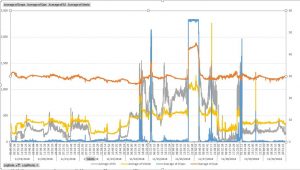
The goesrecv process writes a log file (goesrecv.log) showing various parameters of the signal, error correction, packet counts and drops. I built a small Excel spreadsheet to parse that file and graph the results. Here are our results after a few weeks. Since the antenna is permanently mounted, the changes in Viterbi score are curious – we’re attributing them to weather and wind effects but there are a couple of regular increases in the drop count each day that are still unexplained.  We’re guessing that the long drop on 11/26 may be the result of a rainstorm during that period, but I was concerned that the wind may have knocked the antenna out of alignment with the satellite; consequently I was surprised when the drop count came back down later. There’s still a lot to learn about this whole process. 

Signal quality degrading

In early 2019 we found the signal quality degrading to the point that it’s no longer decodable. Looking at the signal in SDR Console showed it holding at about a 4 db SNR and then unaccountable jumping to about 10 db as shown  below. The change was abrupt and currently unexplained. Needs more research.

References

We looked at a lot of websites and blogs for information about this project.  Below are our notes on sources of information that you may find useful.
https://www.rtl-sdr.com/setting-up-a-goes-weather-satellite-antenna-system/

Receiving GOES Weather Satellite HRIT with an SDRplay and 2.4 GHz WiFi Grid Antenna

Detailed article: https://www.teske.net.br/lucas/2016/10/goes-satellite-hunt-part-1-antenna-system/

Good building options: https://www.rtl-sdr.com/building-a-low-cost-goes-weather-satellite-receiver-with-an-rtl-sdr/

Here’s the link to an antenna: https://www.amazon.com/1850-1990-Parabolic-Antenna-Die-Cast-15dBi/dp/B06ZYJ3P82/ref=sr_1_2?ie=UTF8&qid=1536255463&sr=8-2&keywords=parabolic+grid+antenna+1.9

Link to antenna pointing from W2MMD: https://www.satellite-calculations.com/Satellite/Catalog/catalogID.php?41866

Info on GOES 16, the east-coast satellite: https://en.wikipedia.org/wiki/GOES-16

Video from ThoughtExperiment here: https://www.youtube.com/watch?v=jGWFg7EDnyY

Link to site for satellite aiming: https://www.satellite-calculations.com/Satellite/lookangles.htm

Longer article: http://www.sdrplay.com/community/viewtopic.php?f=5&t=2674

Video of receiving HRPT signals ffrom NOAA satellites: https://www.rtl-sdr.com/receiving-almost-hrpt-with-the-adalm-pluto-and-a-wifi-grid-antenna/

Another blog: http://www.sdrplay.com/community/viewtopic.php?f=5&t=3262&hilit=xrit&start=30

Here’s some info on the GOES 17 satellite – it’s not visible from our location but others may find it useful: https://www.nesdis.noaa.gov/content/noaa-goes-17-shares-first-images-alaska-hawaii-and-pacific

Some general info on the GOES satellites and the telemetry format:
https://medium.com/@luigifcruz/reverse-engineering-goes-16-cda-telemetry-b0234cdfb0c1
http://www.bay-net.org/docs/kk6vxv_goes_baycon_2018.pdf