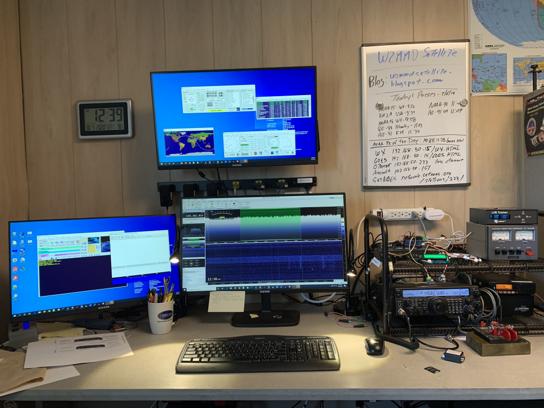
The satellite operating station at the GCARC clubhouse provides many features to facilitate operating the many ham radio satellites. State of the art antennas combined with a station location away from trees means that most satellites can be heard at a few degrees of elevation. SDR receiving allows viewing the entire satellite passband and easy identification of downlink signals and locating other stations. A Yaesu FT-847 is used for transmitting and integration through a RigBlaster audio coupler facilitates working APRS and other digital satellite modes.
Satellite tracking, antenna positioning and Doppler correction is handled by the PST Rotator program running on the satellite station PC. This works with both the SDR Play receiver and the 847 to coordinate frequencies across the uplink and downlink frequencies. PST also handles the antenna tracking through a Yaesu 5500B rotator and LVB tracker. Currently operations are limited to modes V/U and V/U (uplinks and downlinks on 2 meters or 70 cm).
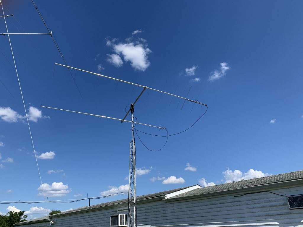
The antennas are the M2 436CP42UG 42-element 70 cm antenna and the 2MCP22 22 element 2 meter antenna mounted on the M2 fiberglass crossboom. Assembling these antennas was a long, complex process especially since the element lengths on the 70 cm antenna didn’t always decrease moving away from the driven element as usually occurs with yagi antennas. Each of the 42 elements had to be carefully measured and installed. Much of the 2 meter antenna had to be assembled outdoors since the assembled antenna wouldn’t fit through the door of the clubhouse. More information about the assembly and mounting of the antenna is at this blog post :https://wp.w2mmd.org/wp/wp-admin/post.php?post=221&action=edit
The Skunkworks team makes frequent use of 3D printing as shown below. Here are two 3D printed racks – one holding the MFJ diplexer that combines the 2 meter and 70 cm antennas going to the SDR receiver, and the other holding the coaxial relays
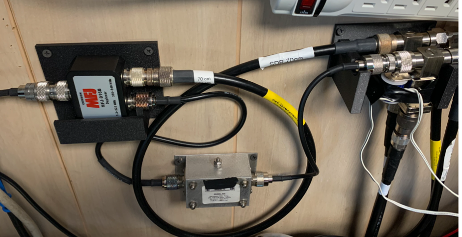
One occasionally-problematic characteristic of satellite operations is the need to switch antennas between transmitter and receiver based on the operating modes of the satellite. Some satellites operate in mode U/V (70 cm uplink, 2 meter downlink) meaning that the 70 cm antenna must be connected to the 70 cm output of the 847 and the 2 meter antenna is connected to the SDR radio. Others operate in mode V/U (2 meters up, 70 cm down) meaning that the 70 cm antenna is connected to the SDR and the 2 meter antenna is connected to to 2 meter output of the 847. Failing to make these changes when switching between satellites can mean that the wrong antenna is connected to the transmitter or receiver – or that no antenna is connected. At best this is suboptimal; at worse it can damage a rig. Using manual antenna switches – one for each band – had so much operator error that we needed to find a better solution.
That solution came in the switchbox shown below. It contains an Arduino Mega microcontroller with a 4-relay “hat”, only two of which are used in this project. The buttons on the box control whether the antennas are in “RX-only” mode meaning that both are connected to the SDR, or in mode U/V or V/U. The operator selects the operating mode and the controller switches the coaxial relays to their proper positions. This functionality replaced the need for switches and made mode switching easier, albeit still requiring manual intervention.
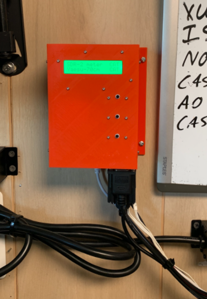
The next step was to make the switching automatic. The PST Rotator program feeds the uplink frequency to the 847 through a CAT cable (in this case a DB-9 connector on the radio), and we added a Y connector to that cable to feed the CAT signal into the Arduino, decode the frequency and discern the operating mode. The Arduino then switches the antennas to the proper configuration based on the satellite selected in PST Rotator, eliminating the operator’s need to deal with the different antenna settings required by the selected satellite.
There was one more step needed, though. APRS operation through the ISS and the NO-84 satellite is on 2 meter simplex, meaning that the 2 meter antenna needed to be switched between the SDR while receiving to the 847 when transmitting. The Arduino could be programmed to handle that logic but needed to know when it was time to transmit. Fortunately the SoundModem program used to create the APRS packets contains the functionality to pull low the RTS pin on a COM port on the PC, so we ran a USB to RS-232 cable from the PC to the Arduino, added a RS-233 to TTL level converter and programmed the Arduino to the 2 meter antenna to the 847 whenever that RTS pin went low. That allows the 847 to transmit the APRS signal on the 2 meter antenna which immediately switches back to the SDR to allow receiving any response. In this way we could handle APRS simplex operation without operator intervention with all of the logical steps programmed into the Arduino.
The orange case for the Arduino was another 3D printed project.
