Or: how we got our QRP Labs beacon working before we understood why it had to be that way
Jon, WB2MNF · Gloucester County Amateur Radio Club
The Problem That Got Us Started
We were running a QRP Labs WSPR beacon at the clubhouse and getting inconsistent results across bands. Spots were coming in on 40 m and 30 m as expected — the beacon was clearly making it out into the world on those bands. But on 20 m, 15 m, and 10 m, nothing. The reception map on WSPRnet showed our beacon making it across the country on the lower bands and then going completely silent on the upper three.
So we hooked an SDR to the antenna feed to see what was actually going out. And the signals were definitely there — but on 20, 15, and 10 m they were sitting roughly 300 Hz above the standard dial frequency for each band. On 40 m and 30 m they were sitting roughly 1500 Hz above the dial. Same beacon, same configuration approach, but two different offsets depending on the band.
We had no idea at the time why the offset mattered or what the “right” offset should be. What we did know was that 40 and 30 m were getting decoded by stations worldwide, and 20/15/10 m were not. The two bands that worked sat at +1500 Hz; the three that didn’t sat at +300 Hz. We didn’t understand why, but we could see the pattern.
So we set out to fix it empirically. The QRP Labs beacon lets you configure the transmit frequency for each band — and the documentation tells you to enter the standard WSPR dial frequency, the same number plastered on every WSPR website. We had done exactly that, and on three bands the unit was producing output that was 1200 Hz lower than it should have been (at dial+300 instead of dial+1500). So we lied to the unit. For each broken band, we entered a configured frequency 1200 Hz higher than the published WSPR dial frequency, and that pushed the actual on-air output up to land at the correct dial+1500 Hz position. Decodes started coming in immediately.
It was a kludge. We were essentially adding a fudge factor on three bands to compensate for behavior we didn’t understand on those bands but that didn’t appear on the other two. The configured frequencies in our QRP Labs unit no longer matched the standard reference numbers — but the on-air signals matched the WSPR network convention, which is what actually mattered.
We still don’t know why the QRP Labs beacon produced different offsets on different bands. The same configuration approach was applied to all five. Whatever caused the difference — a firmware quirk, a settings interaction, a documentation gap, or some combination — we never tracked it down. We had a working beacon and the post-mortem could wait.
The “why does it need to be 1500 Hz at all” question wasn’t solved at a whiteboard. It was solved by working through it with Claude AI, who walked us through the layered frequency model that finally made the whole thing make sense. It turns out the 1500 Hz isn’t arbitrary — it’s a deeply baked convention in how the entire WSPR network operates, and a beacon transmitting at +300 Hz is essentially invisible to every receiver in the world. Once we understood the layered model, we could explain to the next person why their beacon needs to be 1500 Hz above the dial frequency, not at the dial frequency, and not 300 Hz above it either.
This article walks through the layered explanation that finally made it click for us. It applies just as well to FT8, FT4, and any other WSJT-X mode running through a standard SSB transceiver — and to any synthesizer-based beacon that wants to be heard by the WSPR network.
Three Frequencies, Not One
The first thing to internalize is that there isn’t a single “WSPR frequency.” There are at least three numbers, living at three different layers of the system, and they each mean something different.
The dial frequency (14.0956 MHz on 20 m WSPR) is the suppressed-carrier reference point of an SSB radio. It’s not where the signal is — it’s the mathematical zero-point that an SSB transceiver uses to translate audio into RF. Think of it as the bottom edge of the upper-sideband audio passband, mapped onto RF spectrum.
The audio center frequency (1500 Hz) is where WSJT-X chooses to place its FSK tones in the audio passband on the transmit side. This is purely a software convention — it could have been any frequency in the SSB passband, but 1500 Hz is roughly the center, with comfortable margin on both sides for the ±100 Hz F Tol decode window.
The on-air RF frequency is the simple sum: dial + audio = 14.0956 MHz + 1500 Hz = 14.097100 MHz. That’s where the SDR sees the signal. That’s where it actually lives in RF spectrum. And that’s what an SSB receiver tuned to 14.0956 MHz will translate back down to 1500 Hz audio for the decoder.
How SSB Actually Works (the part that always confuses people)
A single-sideband transmitter is a frequency translator. You feed audio into one end, and RF comes out the other end, shifted up to the band of interest. The dial frequency is where audio = 0 Hz would land — except that audio at 0 Hz is just DC, which the audio chain blocks anyway. So the actual audio you can transmit starts somewhere around 300 Hz and goes up to about 2700 Hz, depending on the radio’s SSB filter.
For voice, this is invisible. You speak into the microphone, your voice spans roughly 300 Hz to 2700 Hz, and the SSB radio translates that whole audio band up to (dial + 300 Hz) through (dial + 2700 Hz) on the air. Two operators tuned to the same dial frequency hear each other because the dial-to-RF mapping is the same on both ends. Nobody thinks about specific audio frequencies — they just talk.
Digital modes break that comfortable abstraction. Now there’s software on both ends generating and listening for tones at very specific audio frequencies, and suddenly the mapping matters. WSJT-X generates WSPR audio at 1500 Hz because:
- It’s safely inside any reasonable SSB filter passband (300–2700 Hz)
- It has 1200 Hz of margin on either side, leaving room for the ±100 Hz decode window plus tolerance for receiver mistuning
- It’s far enough from DC that low-frequency hum, 1/f noise, and DC offset don’t intrude
- Everyone agrees on it, so all WSPR transmissions worldwide land in the same 200 Hz RF slice on each band
That last point is what makes WSPR work as a global system. If your station puts WSPR audio at 1500 Hz and my station puts WSPR audio at 1500 Hz and the Australian station does the same, all our signals land in the same RF window (dial + 1400 to dial + 1600 Hz), and any receiver tuned to the dial frequency sees all of us.
Where the 1500 Hz “Offset” Actually Comes From
Here’s the punchline that took us an embarrassingly long time to internalize at the Skunkworks bench:
The 1500 Hz is inserted by the transmitter, not by the receiver.
WSJT-X generates audio tones at 1500 Hz. The SSB transmitter faithfully translates that to (dial + 1500 Hz) on the air. An SDR connected to the antenna sees the signal at (dial + 1500 Hz), exactly where it was put. An SSB receiver tuned to the dial frequency does the inverse translation and recovers 1500 Hz audio. WSJT-X’s decoder sees those tones at 1500 Hz and decodes them.
There is no point in the chain where any device “adds an offset.” The SSB transmitter and receiver are linear frequency translators that perform inverse operations. The 1500 Hz is a number WSJT-X chose for its tones, and it propagates through the chain unchanged.
The reason it’s so easy to get this backwards is that as a user, you experience the 1500 Hz at the receiver. You see it on the WSJT-X waterfall during normal RX operation. It feels like the receiver put it there. But the receiver is just reporting what the transmitter sent. If the WSJT-X authors had picked 800 Hz for their tone center, the waterfall would show tones at 800 Hz and the on-air signals would sit 800 Hz above the dial. Nothing about SSB hardware would change.
A Detail Worth Knowing: Random Offset Within the Sub-band
One more layer that’s easy to miss: WSPR transmitters don’t all sit at exactly +1500 Hz. They sit somewhere in the 200 Hz sub-band, ideally spread out across it.
If every WSPR station in the world transmitted at exactly dial+1500 Hz, all signals would land on top of each other in a single 6 Hz slot, and the decoder would only be able to pull out the strongest one. The whole point of having a 200 Hz sub-band is to let dozens of stations time-share the band by occupying different frequencies inside it.
WSJT-X handles this by letting the operator pick a specific Tx frequency in the 1400–1600 Hz audio range — typically by double-clicking an unoccupied spot in the waterfall before transmitting. Some dedicated beacons (the WsprryPi software for Raspberry Pi, for example) have an --offset flag that adds a random jitter of ±80 Hz to each transmission, so the beacon spreads its signals across the sub-band over time and avoids permanently colliding with another station that happens to use the same frequency.
The QRP Labs beacon and similar synthesizer-based devices typically let you configure where in the sub-band you transmit, and operators often pick a fixed offset somewhere in the 1400–1600 Hz range to avoid the most crowded spots. The +1500 Hz figure used throughout this article is a convenient nominal center; in practice, well-behaved WSPR transmitters spread themselves across the full 200 Hz window.
The takeaway for debugging: when you put an SDR on the antenna and look for your signal, expect it somewhere in the dial + 1400 Hz to dial + 1600 Hz range, not necessarily at exactly +1500 Hz. If you see it 300 Hz above the dial like we did, that’s a problem. If you see it at +1450 or +1550, that’s normal.
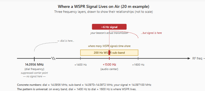
A Frequency-Hierarchy Cheat Sheet for 20 m WSPR
The diagram below shows where each frequency layer lives. The dial readout is on the left — it’s a mathematical reference point with no signal there. The actual WSPR signal lives 1500 Hz higher, inside a 200 Hz sub-band shared by many WSPR stations. The signal itself is only about 6 Hz wide, much narrower than the sub-band that contains it.
| Layer | Frequency | What it is |
|---|---|---|
| Protocol parameter | ~6 Hz | Width of the WSPR signal itself (4-FSK, 1.46 Hz tone spacing) |
| TX audio center | 1500 Hz | Where WSJT-X puts the tones in the audio passband |
| Decode window | 1400–1600 Hz | Audio-frequency range WSJT-X searches |
| WSPR sub-band on air | 14.097000 to 14.097200 MHz | RF slice where many WSPR signals time-share |
| Individual signal on air | ~14.097100 MHz ± 3 Hz | One WSPR signal somewhere in the sub-band |
| Dial frequency | 14.0956 MHz USB | Suppressed-carrier point; what operators tune to |
| SNR reference bandwidth | 2500 Hz | Noise normalization for the −28 dB sensitivity figure (not a real filter) |
For other bands, the structure is identical — only the dial frequency changes. On 40 m, dial is 7.0386 MHz and signals sit around 7.040100 MHz. On 80 m, 3.5686 MHz and 3.570100 MHz. The pattern is always dial + 1500 Hz ± 100 Hz.
What to Tell the Next Person Who Hits This
If a club member fires up a beacon and asks why their signal is in the wrong place, the short answer is:
“Tune your SDR 1500 Hz above the WSPR dial frequency. The dial is the SSB suppressed-carrier point — a mathematical reference, not where the signal actually lives. WSJT-X places its tones at 1500 Hz audio, and the SSB transmitter translates that to (dial + 1500 Hz) on air. Your beacon is doing exactly the same thing. Look at 14.097100 MHz, not 14.0956 MHz.”
The longer answer is everything above. The even longer answer involves working through the layered model with an AI that knows more about RF than any of us — but that’s a story for another Tech Saturday.
Next time you’re at the clubhouse and someone is wondering why their beacon is being heard on some bands and not others, the first thing to check is the offset. If it’s 300 Hz, fix it to 1500 Hz, and the spots will start rolling in. We made the fix the hard way — by spotting the pattern between bands that worked and bands that didn’t — but you don’t have to.
— Jon, WB2MNF
 Save as PDF